![]()
NEW 2023 Certification Sample Questions 4A0-265 Dumps & Practice Exam
4A0-265 Deluxe Study Guide with Online Test Engine
NEW QUESTION # 22
Which of the following statements about the alarm masking mechanism is TRUE?
- A. The alarm masking mechanism makes sure that alarms are always present on the downstream interfaces to facilitate the troubleshooting process.
- B. The alarm masking mechanism updates the events' original time stamps when it masks/shows alarms, so that when an alarm is not masked anymore, the user can see the updated date and time associated with the original issue.
- C. The alarm masking mechanism always forwards masked alarms to an external Network Management System (NMS) for alarm correlation.
- D. The alarm masking mechanism preserves the events' original time stamps, when related alarms gets hidden and then eventually displayed because of the mechanism itself, so that the user can still know the date and time of the original issue.
Answer: D
Explanation:
Explanation
The alarm masking mechanism is a feature of the 1830 PSS that prevents unnecessary alarms from being displayed on the GUI or forwarded to an external NMS when they are caused by a known fault or maintenance activity. For example, if an optical link is down due to a fiber cut, there is no need to show alarms for all the downstream interfaces that are affected by the link failure. The alarm masking mechanism hides these alarms until the root cause is resolved, and then shows them again if they persist. The alarm masking mechanism preserves the events' original time stamps when it masks/shows alarms, so that when an alarm is not masked anymore, the user can see the original date and time associated with the issue. This helps to identify and troubleshoot problems more accurately and efficiently. References : Optical User Guide - Nokia, Alcatel-Lucent 1830 PSS-8 and PSS-16 Photonic Service Switch
NEW QUESTION # 23
What is the default severity level for a Threshold Crossing Alert (TCA) alarm?
- A. Warning
- B. Minor
- C. Major
- D. Critical
Answer: A
Explanation:
Explanation
A Threshold Crossing Alert (TCA) alarm is a type of alarm that indicates that a monitored parameter has crossed a predefined threshold. For example, a TCA alarm can be triggered when the optical power received at a port is too high or too low. The default severity level for a TCA alarm is warning, which means that it does not affect the service but may require attention. The other severity levels are critical, major, and minor, which indicate different degrees of impact and urgency of the alarms. The severity level of a TCA alarm can be changed by the user using the Nokia 1830 Engineering and Planning Tool (EPT) or the Nokia 1350 Optical Management System (OMS). References: Nokia Optical Diagnostics and Troubleshooting Course, Nokia 1830 PSS-32 and PSS-16 Photonic Service Switch Release 8.0 Alarms and Conditions Reference Guide
NEW QUESTION # 24
Suppose a unidirectional amplifier has been plugged into slot 1/13. Which command should the user enter to retrieve the OSC pluggable module type?
- A. show interface 1/13/OSC
- B. show interface 1/13/OSCSFP
- C. show interface 1/13/OSC detail
- D. show interface 1/13/OSCSFP detail
Answer: D
Explanation:
Explanation
The command that the user should enter to retrieve the OSC pluggable module type is show interface
1/13/OSCSFP detail. This command will display detailed information about the OSC interface on slot 1/13, including the type of pluggable module that is installed in it. The pluggable module type can be either SFP or SFP+, depending on the speed and distance requirements of the OSC link. The command will also show other parameters, such as wavelength, frequency, transmit power, receive power, and status. The other commands are incorrect because they either do not show the pluggable module type or have invalid syntax. References: Nokia Optical Diagnostics and Troubleshooting Course, OSFP OCTAL SMALL FORM FACTOR PLUGGABLE MODULE
NEW QUESTION # 25
Which of the following correctly describes how a unidirectional amplification stage works?
- A. * Incoming optical signals are boosted by the ingress amplifier.
* Outgoing optical signals pass through the ingress amplifier but are not boosted. - B. * Incoming optical signals pass through the ingress amplifier but are not boosted.
* Outgoing optical signals are boosted by the ingress amplifier. - C. * Incoming optical signals are boosted by the ingress amplifier.
* Outgoing optical signals are also boosted by the ingress amplifier. - D. * Incoming optical signals are boosted by the ingress amplifier.
* Outgoing optical signals do not pass through the ingress amplifier.
Answer: D
Explanation:
Explanation
A unidirectional amplification stage works by boosting the incoming optical signals by the ingress amplifier, while the outgoing optical signals do not pass through the ingress amplifier. This means that the ingress amplifier only amplifies the signals in one direction, hence the name unidirectional. This configuration is typically used for point-to-point links or ring networks where bidirectional amplification is not required or desired1. References : Nokia Optical Diagnostics and Troubleshooting Course | Nokia
NEW QUESTION # 26
Which of the following statements about using Nokia product documentation in the troubleshooting process is TRUE?
- A. The Customer Release Notes (CRNs) document collects documented solved known issues, new issues discovered after the product software has been released.as well as software upgrade procedures and firmware details.
- B. Before investigating a problem it is important to check the Engineering and Planning Tool User Guide (EPTUG) if a possible issue has already been acknowledged by the Product Unit (PU).
- C. The Customer Release Notes (CRNs) provides instructions to perform the automated provisioning, commissioning, and power balancing functions in a customer network based on the Nokia 1830 PS5 platform.
- D. Before investigating a problem it is important to check the User Provisioning Guide (UPG) if a possible issue has already been acknowledged by the Product Unit (PU).
Answer: A
Explanation:
Explanation
The Customer Release Notes (CRNs) document collects documented solved known issues, new issues discovered after the product software has been released, as well as software upgrade procedures and firmware details. This document is useful for troubleshooting because it can help identify if a problem is related to a known issue or a software bug, and if there is a workaround or a solution available. The CRNs also provide information about the software compatibility and interoperability of different Nokia products and platforms.
The other options are incorrect because the EPTUG and the UPG do not contain information about known issues, and the CRNs do not provide instructions for automated provisioning, commissioning, and power balancing functions. References: Nokia Optical Diagnostics and Troubleshooting Course, Nokia Optical Diagnostics and Troubleshooting Exam
NEW QUESTION # 27
Which of the following commands is used to retrieve the total output power level?
- A. show interface am2125a 1/6/lineout detail
- B. show interface am2125a 1/6/lineout
- C. show interface am2125a 1/6/lineout wavekey
- D. show interface am212 5a 1/6/lineout pm
Answer: A
Explanation:
Explanation
The command show interface am2125a 1/6/lineout detail is used to retrieve the total output power level of the AM2125A amplifier module. This command displays detailed information about the lineout interface, including the current optical power, wavelength, and status. The total output power level is shown as Output Power (dBm) in the output of this command1. References : Nokia Optical Diagnostics and Troubleshooting Course | Nokia
NEW QUESTION # 28
Refer to the exhibit, which shows a conditions list from the 1830 PSS GUI. (i) What is the total number of alarms reported? (ii) How many service affecting alarms are displayed? (iii) How many conditions are displayed?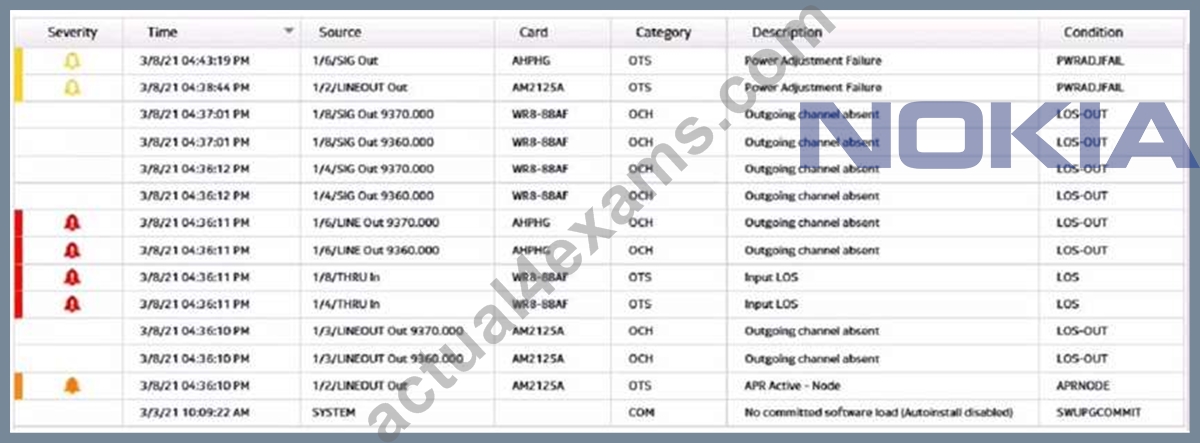
- A. (i) total number of alarms = 4
(ii) number of service affecting alarms = 14
(iii) number of conditions = 2 - B. (i) total number of alarms = 7
(ii) number of service affecting alarms = 5
(Hi) number of conditions = 7 - C. (I) total number of alarms = 5
(ii) number of serviceaffectingalarms = 2
(Hi) number of conditions = 14 - D. (i) total number of alarms = 2
(ii) number of service affecting alarms = 2
(Hi) number of conditions = 18
Answer: B
Explanation:
Explanation
The exhibit shows a conditions list from the 1830 PSS GUI, which displays the alarms and events that occur on the network elements. The total number of alarms reported is equal to the number of rows that have a red or yellow icon in the Severity column, indicating a critical or major alarm. In this case, there are 7 rows with such icons, so the total number of alarms is 7. The number of service affecting alarms is equal to the number of rows that have a "Yes" valuein the Service Affecting column, indicating that the alarm affects the service quality or availability. In this case, there are 5 rows with such values, so the number of service affecting alarms is 5. The number of conditions is equal to the total number of rows in the table, regardless of their severity or service affecting status. In this case, there are 7 rows in the table, so the number of conditions is
7. References : Optical User Guide - Nokia, Security Target Nokia 1830 Photonic Service Switch (PSS)
NEW QUESTION # 29
Which of the following is a passive component in a CDC-F network configuration?
- A. MSH4-FSB Fiber Shuffle Module
- B. IRDM20 Integrated ROADM
- C. WR20-TFM Wavelength Router
- D. 130SCX10 Optical Transponder
Answer: A
Explanation:
Explanation
A passive component in a CDC-F network configuration is the MSH4-FSB Fiber Shuffle Module. This module is used to rearrange the fibers between the CDC-F modules and the wavelength routers, so that each wavelength router can access any of the 96 wavelengths in the C-band. The MSH4-FSB module does not require any power or active components, and it does not perform any optical amplification or switching2. References : Nokia Optical Diagnostics and Troubleshooting Course | Nokia, Nokia 1830 Photonic Service Switch (PSS) | Nokia
NEW QUESTION # 30
Which of the following statements best describes the payload type setting?
- A. Payload type attribute is recorded within the OTN overhead and must be entered manually.
- B. Payload type attribute is recorded within the client payload and must be entered manually.
- C. Payload type attribute Is recorded within the client payload and can be set automatically.
- D. Payload type attribute is recorded within the OTN overhead and can be set automatically or manually.
Answer: C
Explanation:
Explanation
The payload type setting is an attribute that is recorded within the client payload and can be set automatically or manually. The payload type setting indicates the type of client signal that is carried by the OTN frame, such as Ethernet, Fibre Channel, or SDH/SONET. The payload type setting can be used for service identification and performance monitoring purposes. The payload type setting can be set automatically by the ML-Series card, which can detect the client signal type and encode it in the payload header. Alternatively, the payload type setting can be set manually by the user using the command config interface <interface> encmode
<encmode> payloadtype <payloadtype>, where <interface> is the client interface name, <encmode> is the encapsulation mode, such as GFP-F or BMP, and <payloadtype> is the client signal type, such as 10GE LAN or FC-1200. The other options are incorrect because they either state that the payload type setting is recorded within the OTN overhead, which is not true, or that it must be entered manually, which is not necessary. References: Nokia Optical Diagnostics and Troubleshooting Course, OAM and Diagnostics Guide
NEW QUESTION # 31
Which of the following Performance Measurement (PM) type is NOT typically retrieved at an Optical Transponder (OT) line interface?
- A. Ethernet collision counters
- B. Forward Error Correction - Errors Counted (FEC-EC)
- C. Optical Power Received (OPR)
- D. Digital Wrapper (DW)
Answer: A
Explanation:
Explanation
Performance Measurement (PM) is a feature that collects and reports various statistics related to the performance of an optical network element. PM data can be retrieved at different levels, such as Optical Channel (OCh), Optical Channel Data Unit (ODU), Optical Channel Transport Unit (OTU), and Ethernet. An Optical Transponder (OT) is a device that converts an electrical signal into an optical signal and vice versa. An OT has two interfaces: a client interface and a line interface. The client interface connects to the service provider network, while the line interface connects to the optical transport network. At the OT line interface, PM data can be retrieved for the OCh, ODU, OTU, and Digital Wrapper (DW) levels. The DW is a layer that encapsulates the client signal and provides overhead information for monitoring and management purposes.
Ethernet collision counters are not typically retrieved at the OT line interface, as they are related to the Ethernet level, which is usually monitored at the client interface. References: Nokia Optical Diagnostics and Troubleshooting Course, Nokia 1830 PSS-32 and PSS-16 Photonic Service Switch Release 8.0 Performance Monitoring Reference Guide
NEW QUESTION # 32
Suppose a network operator needs to configure the 10GbE client interface 1/7/C1 with a GFP-F encapsulation mode. Which command should be used?
- A. config interface 1/7/C1 tenGige encmode gfp-f
- B. config interface 1/7/C1 encmode 10client gfp-f
- C. config encmode interface 1/7/C1 tenGige gfp-f
- D. config encmode interface 1/7/C1 10client gfp-f
Answer: B
Explanation:
Explanation
The command that should be used to configure the 10GbE client interface 1/7/C1 with a GFP-F encapsulation mode is config interface 1/7/C1 encmode 10client gfp-f. This command will set the encapsulation mode of the interface to GFP-F, which is a frame-mapped generic framing procedure that encapsulates Ethernet frames with a GFP header. The command also specifies that the interface is a 10GbE client interface, which means that it supports 10 Gigabit Ethernet LAN signals. The other commands are incorrect because they either have invalid syntax or use incorrect parameters for the interface or the encapsulation mode. References: Nokia Optical Diagnostics and Troubleshooting Course, OAM and Diagnostics Guide
NEW QUESTION # 33
Suppose a channel-related alarm is reported on an 1830 PSS node, and is related to a possible Wave Keys clock source issue. What is the recommended order for the following troubleshooting steps?
- A. 1. Retrieve the channel power trace.
2. Determine the active clock reference source.
3. Switch to alternate clock source (PF).
4. Replace the suspect PF. - B. 1. Determine the active clock reference source.
2. Replace the suspect PF.
3. Retrieve the channel power trace.
4. Switch to alternate clock source (PF). - C. 1. Retrieve the channel power trace.
2. Replace the suspect PF.
3. Determine the active clock reference source.
4. Switch to alternate clock source (PF). - D. 1. Replace the suspect PF.
2. Retrieve the channel power trace.
3. Switch to alternate clock source (PF).
4. Determine the active clock reference source.
Answer: A
Explanation:
Explanation
The recommended order for the troubleshooting steps is A, as follows:
* Retrieve the channel power trace. This step is useful to identify the affected channel and its power level, as well as to check if there are any fluctuations or anomalies in the power trace that could indicate a clock source issue1.
* Determine the active clock reference source. This step is necessary to verify which clock source is currently used by the node, and if it matches the expected configuration. The clock source can be either a local oscillator (LO) or a phase-locked loop (PLL) that synchronizes with an external reference2. The active clock source can be determined by using the command show interface ot 1/1/lineout detail3.
* Switch to alternate clock source (PF). This step is helpful to isolate the problem and confirm if the suspect PF is indeed causing the channel-related alarm. By switching to an alternate clock source, such as another PF or an external reference, the node can recover from the alarm if the original clock source was faulty4.
* Replace the suspect PF. This step is the final solution to resolve the issue and restore the normal operation of the node. The suspect PF should be replacedwith a new one that has the same specifications and configuration as the original one5. References : Nokia Optical Diagnostics and Troubleshooting Course | Nokia, Optical User Guide - Nokia, Alcatel-Lucent 1830 PSS-8 and PSS-16 Photonic Service Switch
NEW QUESTION # 34
Consider the exhibit which shows an EPT Power Management Report referring to an ingress amplifier. What is the available output optical power range?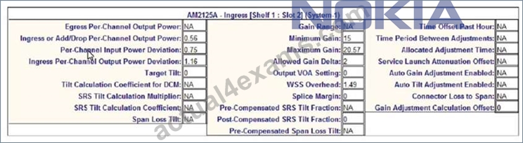
- A. 0.56 to 1.14 dB
- B. -0.02 to 1.14 dB
- C. 0.56 to 1.72 dB
- D. -0.6 to 1.72 dB
Answer: D
Explanation:
Explanation
The available output optical power range is the same as in question 5, since the EPT Power Management Report refers to the same ingress amplifier with the same settings and parameters. Therefore, the answer is also A, -0.6 to 1.72 dB. References : Nokia Optical Diagnostics and Troubleshooting Course | Nokia, EPT Power Management Report | Nokia
NEW QUESTION # 35
Consider the exhibit which shows part of an EPT Schematic View. Which number refers to the Wavelength Router (WR8-88) block?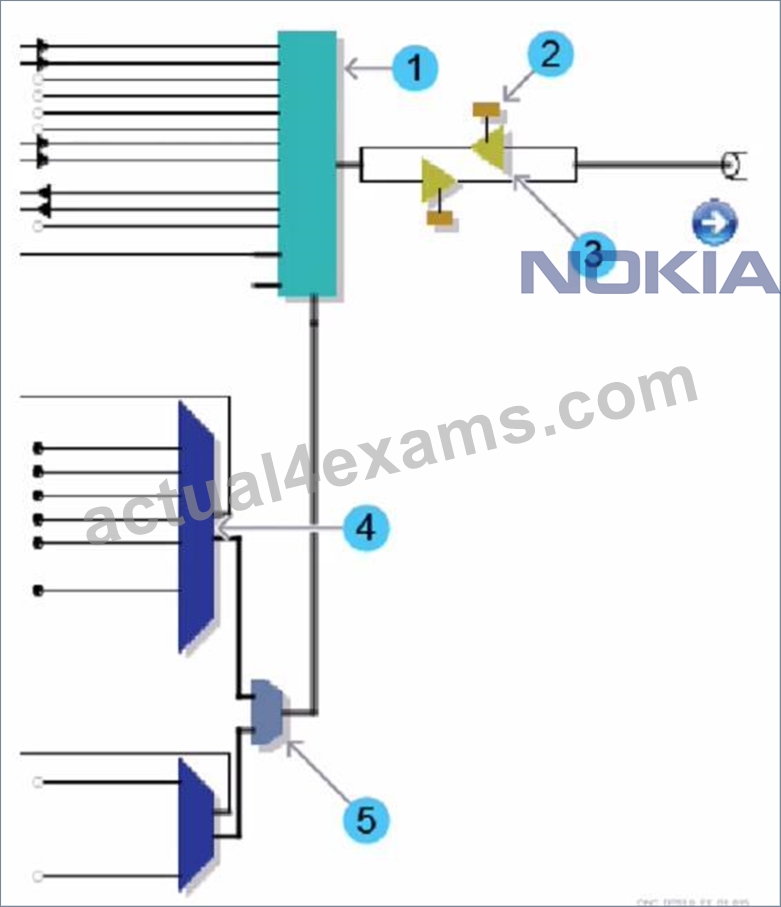
- A. 0
- B. 1
- C. 2
- D. 3
- E. 4
Answer: C
Explanation:
Explanation
The Wavelength Router (WR8-88) block is a device that can route optical signals based on their wavelengths.
It can also perform wavelength conversion, multiplexing, and demultiplexing functions. The Wavelength Router (WR8-88) block is part of the Nokia 1830 PSS-8x platform, which is optimized for metro aggregation switching applications in optical transport networks1. In the exhibit, the number 1 refers to the Wavelength Router (WR8-88) block, as indicated by the label WR8-88AF. The other numbers refer to different components of the system, such as transponders, amplifiers, and switches. References: Nokia Optical Diagnostics and Troubleshooting Course, DWDM 1830 PSS-8 WR8-88AF Board
NEW QUESTION # 36
Consider the exhibit.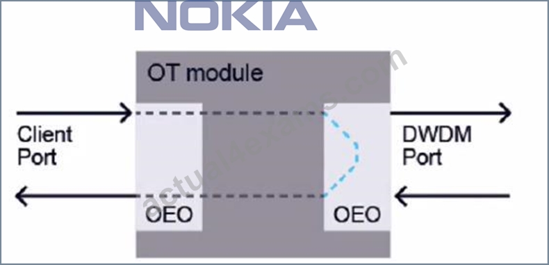
Which type of loopback is applied?
- A. Line port facility Ioopback
- B. Line port terminal Ioopback
- C. Client port terminal Ioopback
- D. Client port facility loopback
Answer: C
Explanation:
Explanation
The exhibit shows a diagram of an OT module with a client port and a DWDM port. The client port is looped back to itself with an OEO (Optical-Electrical-Optical) device. This means that the signal received by the client port is converted to an electrical signal, then back to an optical signal, and then transmitted back to the same port. This type of loopback is called a client portterminal loopback. It is used to test the functionality of the client port without involving the DWDM port or any other network element4. A client port facility loopback would involve looping back the signal from the DWDM port to the client port. A line port facility loopback would involve looping back the signal from another OT module or network element to the DWDM port. A line port terminal loopback would involve looping back the signal from the DWDM port to itself5. References : Nokia Optical Diagnostics and Troubleshooting Course | Nokia, Loopback - Wikipedia
NEW QUESTION # 37
Which of the following issues can cause a "Loss too low" message to be displayed after a power adjustment has been provided?
- A. An incorrect EPT network design
- B. Unstable optical power levels
- C. A dirty fiber connector
- D. A defective WSS unit
Answer: B
Explanation:
Explanation
A "Loss too low" message can be displayed after a power adjustment has been provided if there is an issue with unstable optical power levels. Unstable optical power levels can be caused by various factors, such as environmental conditions, fiber aging, equipment malfunction, or configuration errors. Unstable optical power levels can affect the accuracy and reliability of the power adjustment process, which relies on measuring the optical loss between two points in the network. A "Loss too low" message means that the measured optical loss is lower than the expected value, which can indicate a problem with the optical signal quality or integrity.
The other issues are incorrect because they either cause a different type of message or do not affect the power adjustment process. References: Nokia Optical Diagnostics and Troubleshooting Course, OAM and Diagnostics Guide
NEW QUESTION # 38
......
4A0-265 dumps review - Professional Quiz Study Materials: https://www.actual4exams.com/4A0-265-valid-dump.html